| IP Kamera M12 - Dnevno noćna IP kamera |

Dva oka. 100,000 razloga.
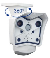
Mobotix dnevno – noćna IP kamera sa dva sočiva i dva potpuno odvojena HiRes fotosenzora, uspešno je instalirana na preko 100.000 lokacija širom sveta. Brilijantna boja na dnevnom svetlu i izuzetno osetljiv crno-beli seznor za noćni režim rada. Inteligentno i robustno profesionalno rešenje bez pokretnih delova.


Mobotix HiRes IP kamera može da zameni i do 6 analognih kamera
- Dva potpuno odvojena fotosenzora za dnevni i noćni režim rada • Integrisan DVR sa HiRes modom snimanja
- Trajno fabrički fiksirana sočiva za jednostavnu instalaciju
- Robustan, bez potrebe za održavanjem i otporna na sve vremenske uslove (-30° do +60°C (-22° to +140°F) i bez potrebe za grejanjem
- Digitalni zum, pan i tilt
- Integrisan mikrofon, zvučnik i PIR detektor pokreta

* ゥ MOBOTIX AG ・Information subject to change without notice! ・MSRP (Manufacturer壮 suggested retail prices) ・ex-works Kaiserslautern, Germany (EXW) ・excluding VAT and any other handling charges ・7/2008


| Mounting Options | |
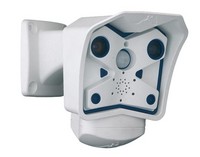
Mounting to a wall |
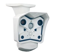
Mounting to a Ceiling |
|
|
|
|
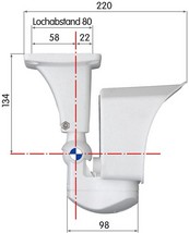
Tilting (wall mount) |
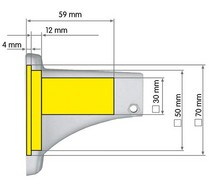
Tilting (ceiling mount) |
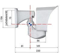
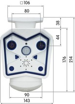
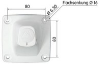
| Dimensions | |
The SecureFlex mount enables easy mounting of the MOBOTIX M12 models to a wall or ceiling; the concealed cabling enhances the visual impression of the installation. The foot of the supplied wall mount is large enough to elegantly cover wall outlets.
|
|
|
|
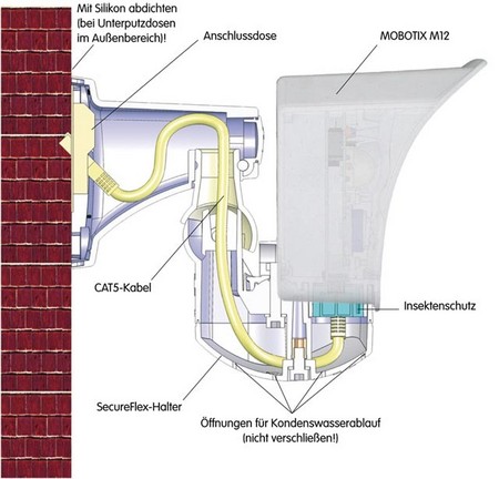
| Mounting Instructions | |
Mounting the Camera over Wall Outlets
 Mounting the SecureFlex mount to a wall allows covering RJ45 wall outlets (without frame) and also allows using a defined network end point.
When positioning the wall outlet, make sure that the outlet lines up with the upper rim of the mount later on (see figure below and the drilling template at the end of the manual).
If no wall outlet is present, use a suitable extension or an adapter to connect the camera to the network.
When installing an above-the-wall assembly, breaking out one of the four openings in the base of the mount will provide for properly guiding the cable into the mount.
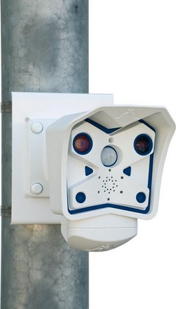
Mounting on the Pole Mount
If you are intending to mount the camera on a pole, you should consider using the MOBOTIX SecureFlex Pole Mount. This mount is made of 3 mm powdercoated stainless steel (white) and has been designed specifically for outdoor use. The supplied stainless steel straps allow fixing the mount to poles with diameters between 60 and 180 mm (2.4" to 7.1").
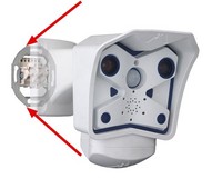
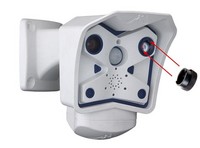
| Adjusting the Tele Lens Focus | |
OHow to recognize the 135 mm tele lens: The 135 mm tele lens has two notches opposite from one another and is not covered by a glass pane. It can be removed using the supplied adjustment ring, which is also used for adjusting the tele lens focus.
Once the camera has been mounted, the tele lens should be checked for proper sharpness and should be adjusted, if required. Make sure that you have the supplied adjustment ring ready for this purpose.
|
|
| Connecting the camera | |
The MOBOTIX camera does not require any software installation; all you need is your preferred browser with JavaScript support to operate the camera. Thus, the MOBOTIX camera is supported by all common operating systems (such as Windows, Macintosh and Linux, ...).
If the camera is supplied with Power over Ethernet (a PoE switch), then no other device will be necessary for supplying power.
Establishing the Power Supply to the Camera
You can choose between the following options:
- External power supply and Network Power Adapter (MX-NPA-3-RJ): Power supply of one camera injected into the network cabling (max. length 100 m (110 yd)), from the NPA to the 10BaseT/NET connector of the camera.
- Network Power Box/Rack (MX-NPR-4, or 8/20): Power supply of 4/8/20 cameras injected into the network cabling (max. length 100 m (110 yd)), from the NPR to the 10BaseT/NET connector of the camera.
- Power over Ethernet: Power supply using network components that are conforming to the PoE standard.
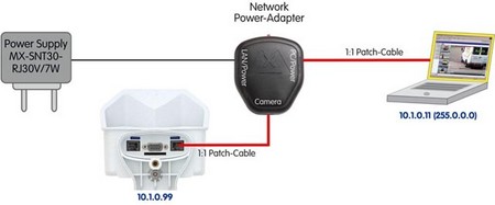
Power Supply (MxPoE) Using a Switch
- Connect the factory pre-installed cable of the camera to the Camera connector of the Network Power Adapter.
- Connect the LAN/Power connector of the Network Power Adapter to an Ethernet connector of the switch/router or the Ethernet wall outlet.
- Plug the RJ45 connector of the external power unit into the PC/Power connector of the Network Power Adapter.
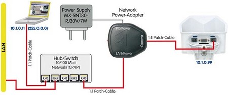
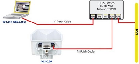
Power Supply (MxPoE) When Connected Directly to a Computer
- Connect the factory pre-installed cable of the camera to the Camera connector of the Network Power Adapter.
- Connect the PC/Power connector of the Network Power Adapter to the Ethernet port of the computer.
- Plug the RJ45 connector of the external power unit into the LAN/Power connector of the Network Power Adapter.
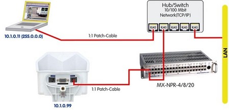
Power Supply (MxPoE) Using a Network Power Rack or Network Power Box
- Connect the factory pre-installed cable of the camera to the CAM connector of the Network Power Rack (MX-NPR-8/20) or the Network Power Box (MX-NPR-4).
- Connect the LAN connector of the Network Power Rack or Network Power Box to an Ethernet connector of the switch/router.
Power Supply (PoE IEEE 802.3af) Using Power-over-Ethernet Products
Connect the factory pre-installed cable of the camera to the Ethernet connector of the PoE switch/router. The switch/router needs to support the PoE standard IEEE 802.3af.
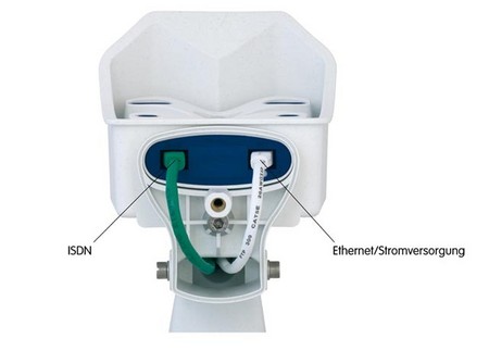
ISDN: Power Supply Using a Network Power Adapter
- Push the designated connector of the ISDN split cable (MX-OPT-ISDN-SPLIT; optional accessory) into the 10BaseT/NET connector and the remaining cable into the ISDN connector of the camera.
- Use an 8-wire (patch) cable to connect the Camera connector of the Network Power Adapter to the socket of the ISDN split cable.
- Connect the LAN/Power connector of the Network Power Adapter to the ISDN S0 bus/NT.
- Plug the RJ45 connector of the external power unit into the PC/Power connector of the Network Power Adapter.

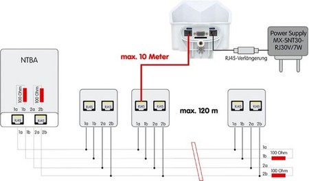
Maximum Cable Lengths (ISDN):
- Connection to ISDN outlet: max. 5-10 m (16 to 33 ft.)
- Connection to NT (without termination resistors): max. 5-10 m (16 to 33ft)
- Connection to NT (with termination resistors): 120 m (130 yd)
Missing termination resistors and wrong cable lengths are the most common installation errors! Always observe the instructions regarding maximum cable lengths and proper ISDN termination!
ISDN: Directly Supplying Power Using the External Power Supply
- Connect the ISDN connector of the camera to the S0 bus/NT.
- Plug the RJ45 connector of the external power supply into an RJ45 extension cable and plug the extension into the 10BaseT/NET connector of the camera.
Ethernet and ISDN
In order to use Ethernet and ISDN simultaneously, plug the Ethernet and ISDN cables into the corresponding connectors of the camera. Power is supplied only via the Ethernet cable and the 10BaseT/NET connector of the camera (using MOBOTIX PoE products or Power over Ethernet according to IEEE 802.af)